Schematics
| Full Detail Schematics |
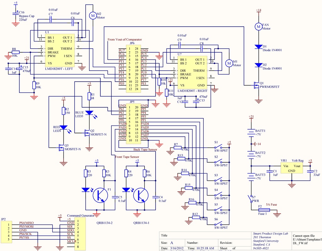
Figure 6: Complete Schematic, except for IR beacon detection circuit
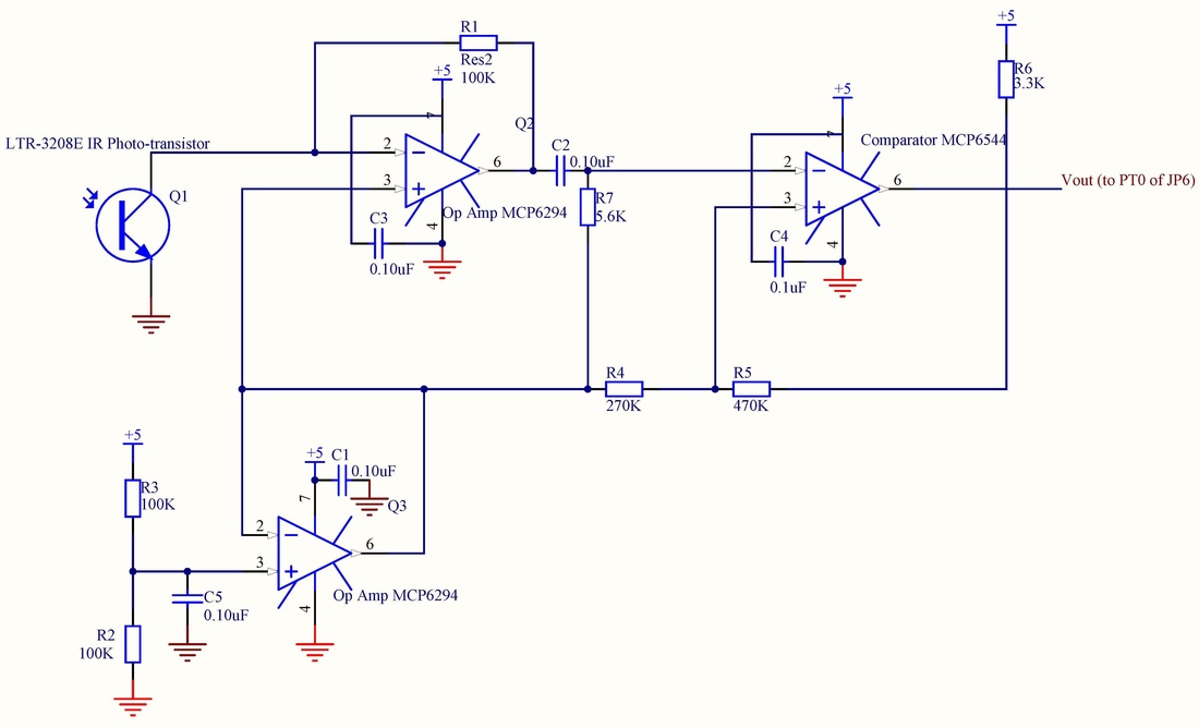
Figure 7: IR Beacon Detection Circuit
IR Detection Circuit
In order to identify scoring bins, an IR detection circuit was designed. The circuit filtered and amplified an incoming IR signal using an operational amplifier wired in a trans-resistive circuit (upper left part of Figure 7), a virtual ground (lower left), a high-pass filer (made from C2 and R7), and a Schmitt Trigger (upper right). The signal was crisp enough so that the period of the emitted signal could be determined and the scoring bin could be uniquely identified.
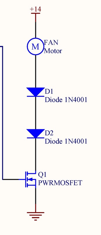
Detailed view of the fan circuit, an H-Bridge, and power distribution
Power to the fan was controlled by the micro-controller using an N-Channel MOSFET. Two series diodes were added to ensure the voltage across the fan was within the manufacturer's 13.2V specification.
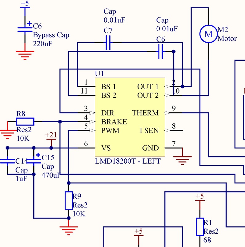
The LMD 18200 H-Bridges were chosen because of their relatively low voltage drop (high efficiency). Two bootstrap capacitors were added to stabilize the power applied to the motors, and bypass capacitors were used to reduce noise interference.
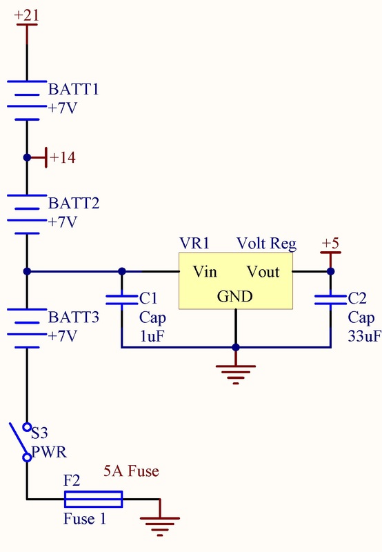
The robot was autonomous, so battery power was essential. Three 7.2V batteries were wired in series to meet various power requirements. A single battery was used to power a 5V regulator, since 5V was necessary for digital circuitry. Two batteries wired in series were used to power the fan and micro-controller. Three batteries in series were used to power the Maxon motors necessary for locomotion.
The LMD 18200 H-Bridges were chosen because of their relatively low voltage drop (high efficiency). Two bootstrap capacitors were added to stabilize the power applied to the motors, and bypass capacitors were used to reduce noise interference.
The robot was autonomous, so battery power was essential. Three 7.2V batteries were wired in series to meet various power requirements. A single battery was used to power a 5V regulator, since 5V was necessary for digital circuitry. Two batteries wired in series were used to power the fan and micro-controller. Three batteries in series were used to power the Maxon motors necessary for locomotion.
Close up of bump sensors, team ID LEDs, and tape sensors
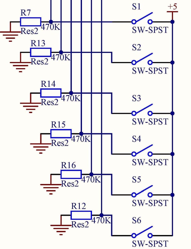
Bump sensors (limit switches) sent a high voltage signal to the micro-controller when closed. When open, a low voltage signal was sent to the micro-controller, by way of a pull down resistor.
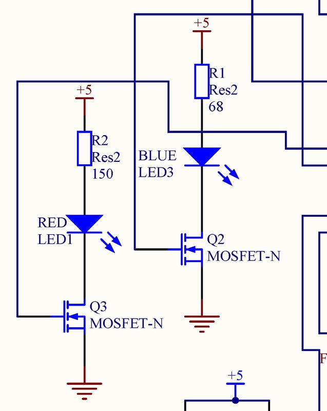
LEDs were controlled by the micro-controller using N-Channel MOSFETs. Current limiting resistors were in series with the LEDs to ensure the appropriate amount of current flowed through each LED (note that different color LEDs require different currents).
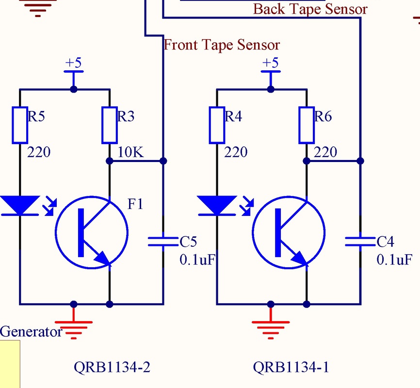
Tape sensors are actually two components in one package -- an IR LED and a phototransistor calibrated to detect black vs. white surfaces. These sensors were used to roughly navigate the playing field.
LEDs were controlled by the micro-controller using N-Channel MOSFETs. Current limiting resistors were in series with the LEDs to ensure the appropriate amount of current flowed through each LED (note that different color LEDs require different currents).
Tape sensors are actually two components in one package -- an IR LED and a phototransistor calibrated to detect black vs. white surfaces. These sensors were used to roughly navigate the playing field.
